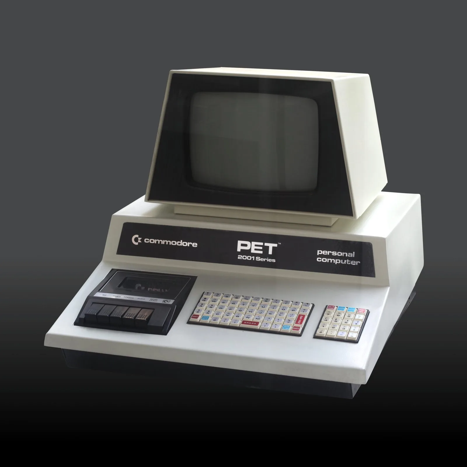
Lift the lid of a Commodore PET 2001 and the first thing you notice is how little is going on. There is a transformer, a tape deck, a CRT with a warning label that deserves to be read twice and a logic board that looks more like a piece of telephone exchange than a personal computer. It is all discrete parts and sockets. Nothing has been hidden inside a custom chip, because in 1977 there were no custom chips to hide it in.
So is the PET’s design worth understanding properly, rather than admiring from a distance? Yes, and for a practical reason: almost everything that goes wrong with one follows directly from a decision that made sense at the time. Know the design and the fault list more or less writes itself. This piece sticks to the hardware.
A note on method. What follows is a teardown analysis built from schematics, published repair records and the community documentation that has grown up around the machine. It is not a log of a PET on my own bench, and nothing here should be read as one.
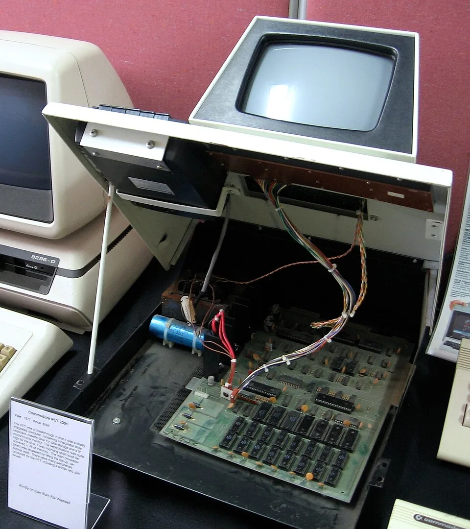
A 6502, an 8 MHz crystal and a memory map you can memorise
The CPU is a MOS Technology 6502 at 1 MHz. The board’s master clock runs at 8 MHz, and both the processor clock and the video timing are divided down from it. That is the first hint that the video circuit and the CPU share more than a power rail.
The memory map is admirably tidy. RAM starts at $0000 and runs to $7FFF on a fully expanded machine, though a stock 2001 shipped with 4 KB or 8 KB. Screen memory sits at $8000, 1 KB mirrored across a 4 KB block. Three sockets at $9000, $A000 and $B000 take optional ROMs. BASIC lives at $C000 to $DFFF, the screen editor at $E000 to $E7FF and the Kernal at $F000 to $FFFF, with the I/O window bitten out of the middle at $E800.
Inside that I/O window sit two 6520 PIAs, at $E810 and $E820, and one 6522 VIA at $E840. The first PIA handles the keyboard and cassette control, the second runs the IEEE-488 bus and the VIA covers the user port plus a handful of odd jobs. The VIA also reads the video retrace signal, which is why one famous line of BASIC causes so much trouble later.
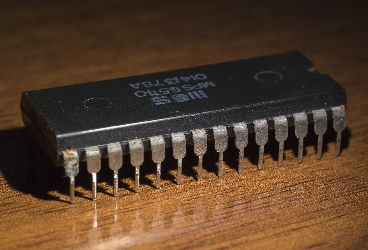
RAM on the earliest boards is the MOS 6550, a 1024 by 4-bit static part, so each kilobyte takes two chips. An 8 KB machine therefore carries sixteen for main memory plus two more for the video RAM. ROM is the 6540, a 2 KB mask ROM in a ceramic package. Both are rarer than they ought to be now. Later boards moved to standard 2114 static RAM and then dynamic RAM, and to ordinary 2316-type ROMs.
The video circuit that has no video chip
There is no CRT controller on the original 2001. The display is built from counters. The 8 MHz clock drives a divide-by-eight counter that triggers a shift register once per character, a 10-bit address counter walks through the 1000 bytes of screen RAM, and a 3-bit counter tracks which of the eight scan lines of the current character row is being drawn. Each scan line takes 64 CPU cycles: 40 for the visible columns and 24 for blanking. The frame rate comes out at about 60.1 fields a second, derived from the CPU clock rather than the mains.
Each byte fetched from screen memory does two jobs. The lower seven bits address the character ROM, which on early boards is a 6540-010, and the top bit drives an inverter to give reverse video. A line called GRAPHIC feeds the top address line of the character ROM and switches between the graphics set and the lower-case set, and it is the 6522’s CA2 output that flips it. That is a complete text display, PETSCII graphics included, built from a handful of counters, a latch, a shift register and a ROM. I count it among the neatest pieces of constraint engineering of the decade.
It has one honest weakness. The screen RAM has to serve two masters, and on the first board revision it cannot serve both at once. When the CPU needs the screen memory it takes over the address lines, and whatever byte sits at that location flashes on the display as noise. That is the ‘snow’ every early PET owner remembers. Later boards fitted faster video RAM so the display could read during the first half of each Phi2 cycle and the CPU could have the second half, which cured it.
The killer poke and the snow it was hiding
The first boards’ answer to snow was for the Kernal to wait. Before writing to the screen it checks a retrace flag from the VIA’s port B, and only writes during vertical blanking. Correct, and slow.
POKE 59458,62 is the famous cheat. Address 59458 is $E842, the data direction register for port B, and the value makes PB5 an output driven low. The Kernal reads an output pin’s register value rather than the pin itself, so it now believes the beam is permanently in retrace and writes to the screen at full speed. Screens redraw far faster, at the price of some snow. On a 2001 or a 3000 series machine that is the whole story.
On the later CRTC boards the same pin carries vertical sync, so the poke drags the display out of step and can collapse the picture into a bright horizontal line. Folklore says it could destroy the monitor, and 6502.org’s write-up leans into the smoke-and-fire version. Wikipedia’s entry on the poke says it is not known to have caused permanent damage. I would not type it into a 4000 series machine to find out.
The keyboard, the tape deck and everything in the lid
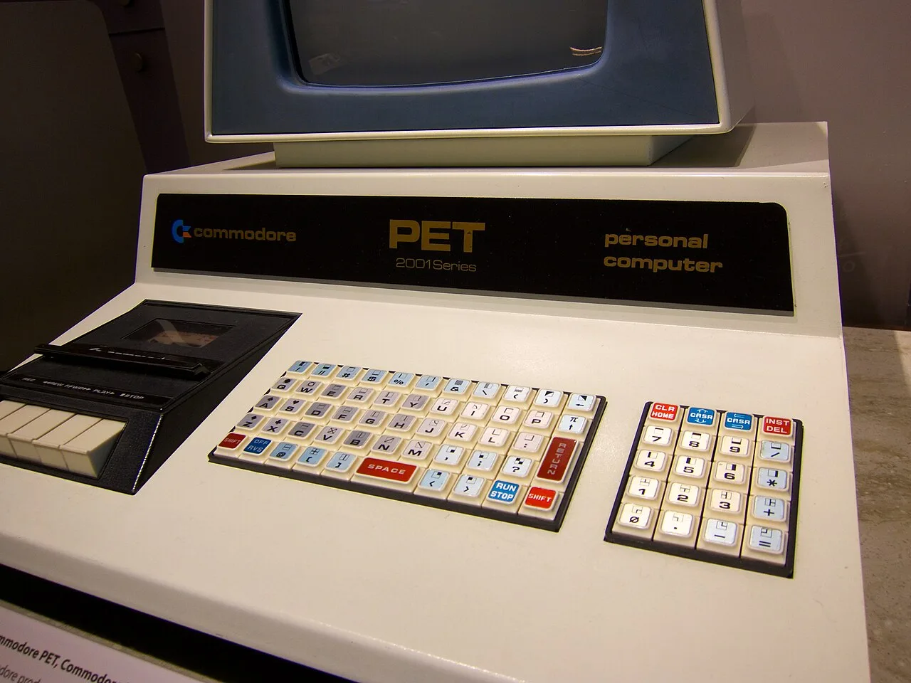
The chiclet keyboard has had its reviews. Mechanically it is simple: a circuit board with contact pads, in a matrix of eight columns by ten rows, scanned by a 74LS145 that turns three lines from the PIA into ten row selects. It is usually quoted as 73 keys including the separate numeric pad, though Wikipedia’s PET article says 69. Being a matrix, its failures are logical. A dead row or column points at the connector or the decoder before it points at any single key. One documented repair found the 74LS145 with every output stuck low, so no row was ever selected. Most other cases are cured by cleaning the pads.
The early 2001 also carries a built-in cassette deck at the left of the front panel, an ordinary transport wired to the PIAs, with motor control on the first PIA’s CB2 line. The deck is the reason the keyboard has so little room, and the reason the 2001-N of 1979 moved tape to a port on the back. Belts perish and heads oxidise, exactly as in a hi-fi from the same year. The transfer rate is quoted as 1500 baud, halved to 750 in practice because everything is recorded twice for safety.
How 6540 and 6550 chips die
These two chip types earn the PET its reputation for temperament. The 6550’s several enable lines can fail so that the chip is permanently selected, and it then drives the data bus at the same time as whatever is meant to be talking. Bus contention is not subtle. It fills screens with characters or leaves a machine reporting far less memory than it has. In one published repair of a 2001-8 the machine booted with only 1102 bytes free until the RAM chips were shuffled to clear an overlap in the address space. Another write-up records fourteen of eighteen 6550 chips bad, and a third has four of seven ROMs dead.
Contention runs downhill. Chips fighting each other run warm, and warm chips fight harder. A failing 6540 or 6550 can cook itself and its neighbours, and the heat shows up at the 5 V supply as well. Ceramic packages in old sockets add a second fault type: the socket loses contact pressure and the machine hangs or shows garbage until the pins are cleaned or the socket replaced.
A garbage screen is not always RAM, though. A display full of characters that look nearly right can be read against a PETSCII table. If every wrong glyph has bit 4 set, the video RAM chip holding that bit is the suspect. Snow that appears when the CPU touches the screen sent one repairer to the 74LS157 multiplexers that arbitrate between CPU and display access to video RAM, where one output was stuck high. Three of them do that job, and they have a habit of failing.
The power side: what to check before you switch on
Two warnings first. Mains voltage is present on the display assembly whenever the machine is plugged in, and the CRT anode holds roughly 10 kV after switch-off. Discharge it properly or leave it to someone who has.
The 2001 has no separate power supply box. The mains transformer, rectifiers and a large reservoir capacitor live on the display assembly beside the flyback transformer, and the logic board is fed ready-made rails. Sources disagree on the details. Tynemouth Software describes a centre-tapped 9 V AC winding, two diodes and 7805 regulators on tall vertical heatsinks. RetroTech Collection lists 1N5402 rectifiers, a 4700 microfarad reservoir and says no regulator sits on the logic board at all. Both agree the logic board should not be the first thing you blame.
The routine is the same as for any 45-year-old linear supply. Inspect the electrolytics near the transformer before power goes on, and check the fuse is the right type. Bring the machine up slowly, ideally through a lamp limiter, and measure 5 V at the 6502’s supply pin before trusting anything. If the rail sags, pull the RAM and ROM chips out group by group and see whether it recovers. That finds contention faster than any amount of staring.
On the logic board itself the electrolytics are few: four 47 microfarad 16 V parts and four 1 microfarad 25 V tantalums, per RetroTech Collection. Replace tantalums with tantalums.
A repair approach that starts with the screen
The order that emerges from the published repairs is consistent. Check the rails. Take the CPU out and see what the video circuit does on its own, since a stable pattern on a headless board says the counters, shift register and character ROM are healthy. Run a diagnostic ROM if you have one, because a built-in video RAM test beats guessing. Swap suspect 6520 and 6522 parts for WDC equivalents. Replacement boards for the 6550 video RAM and the 6540 character ROM exist, and you should expect to need them, because a 45-year-old supply of the originals is finite.
Verdict
The PET 2001 is a beautifully honest machine. Every signal the CPU sees is on a socket you can reach with a probe, and the video circuit can be traced with a finger and a schematic. It also carries the fingerprints of a hard schedule. The first ROM set shipped with an IEEE-488 interface that did not work, and the first board’s video design made software choose between waiting for retrace and living with snow. Those are the marks of a good engineering team working to a very short deadline, and I have no complaint about the team. I would happily own one. I would just prefer to own it after somebody else had replaced the sockets.