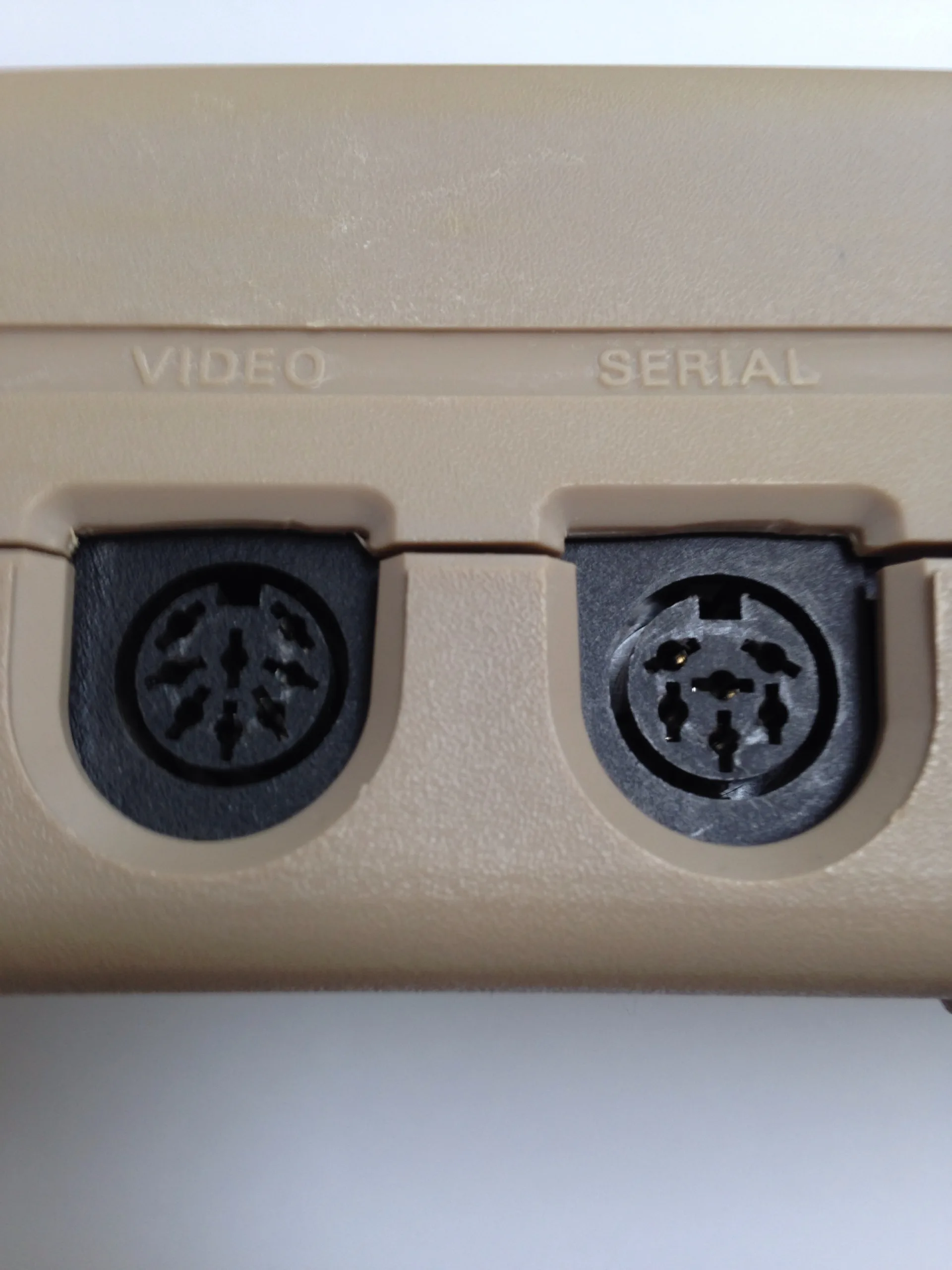
You don’t need to open the computer. The Commodore 64’s picture comes out of its A/V port, and a cable with the right pins joined to the right resistors gives you composite or S-Video without a single solder joint on the board. What you get depends on which port your machine has.
Early C64s have a 5-pin DIN socket. Later ones have an 8-pin DIN with the same pins plus a true chroma signal on pin 6. Wikipedia says early machines used the 5-pin port and later revisions the 8-pin one.
Which pins carry what?
Radagast’s repair pinouts, which match the pinout summaries in my search results, give the 5-pin socket like this:
- Pin 1: luminance.
- Pin 2: ground.
- Pin 3: audio out.
- Pin 4: composite video out.
- Pin 5: audio in.
The 1985 service manual text confirms audio out on pin 3 and audio in on pin 5. The 8-pin socket adds pin 6, chroma out, and leaves pin 7 unconnected. Pin 8 is where sources disagree. Radagast says it carries a power supply line on the C64C and C128, and other pages say pins 7 and 8 are not connected. Leave pin 8 alone either way.
What do you need?
- An 8-pin or 5-pin DIN plug that matches your socket, or a ready-made cable.
- RCA plugs, or a 4-pin mini-DIN S-Video plug.
- Screened cable.
- A soldering iron, and a multimeter to check for shorts.
- Resistors: 150 ohm and 330 ohm (or 300 ohm) from the sources below.
How do you make a composite cable?
- Identify your socket. Count the pins. Five means an early machine, eight means a later one.
- Wire the picture. Join pin 4 to the centre of a yellow RCA plug.
- Wire the ground. Join pin 2 to the outer of every RCA plug on the cable.
- Wire the sound. Join pin 3 to a white RCA plug, and use pin 5 only if you want audio in.
- Test with a multimeter. Check for continuity on each wire and for no short between signal and ground.
How do you make an S-Video cable?
S-Video keeps the picture’s brightness and colour on separate wires. The standard 4-pin mini-DIN carries ground on pins 1 and 2, luma (Y) on pin 3 and chroma (C) on pin 4, according to Wikipedia. Radagast’s page lists the S-Video pin functions the other way round for its own crossover cable. I’ve used the standard, and if you get a black and white picture, swap the two signal wires.
- Ground. Join C64 pin 2 to S-Video pins 1 and 2.
- Luma. Join C64 pin 1 to S-Video pin 3. The Retro Computer Tinkerer’s 5-pin cable put 150 ohms in this line, while RandyInLA’s account mentions a resistor only on chroma.
- Chroma, 8-pin machine. Join C64 pin 6 to S-Video pin 4, through a resistor of 300 to 330 ohms.
- Chroma, 5-pin machine. Use pin 4 through 330 ohms, as the Tinkerer did. It is composite, so it still contains luma.
- Sound. Run pin 3 to an RCA plug for audio, if your display wants it separately.
- Test. Check continuity and for shorts before you plug it into the computer.
Why are those resistor values what they are?
They come from hobbyist write-ups. RandyInLA writes that on a US NTSC breadbin with an 8-pin port, a single 300 ohm resistor on pin 6 stopped the artefacts, with no board change. The Retro Computer Tinkerer used 150 ohms on luma and 330 ohms on chroma for a 5-pin machine, and measured the stock luma at 1.52 V peak to peak before attenuating it. Commodore.net puts 330 ohms on the chroma line of its own cable, which is made for the C64 Ultimate.
Radagast’s page gives no resistor values and calls the procedure experimental. Start with the values above, look at the picture, and change them if it is too dim or too bright.
Why does a 5-pin machine look worse?
Because pin 4 is composite. Used as chroma, it carries the luma signal along with it, and RandyInLA describes the result as jaggy, jpg-like artefacts. Only the 8-pin socket has a clean chroma output on pin 6.
What if it still looks wrong?
- A black and white picture: swap the luma and chroma wires.
- Heavy colour fringing: try a different resistor on the chroma wire.
- No picture at all: check for a break, and check you are on the right pin.
- A picture that disappears when you wiggle the plug: reflow the joints on the DIN plug.
The Retro Computer Tinkerer also claims that resistor R10 on the 326298 board is a 300 ohm factory error and should be 120 ohms. That is a single, unverified account, and I wouldn’t touch the board on its say-so.
What should you check afterwards?
- Brightness and colour on the display you actually use.
- That the audio works on both channels you wired.
- That the plug is firmly seated, with no strain on the solder joints.