
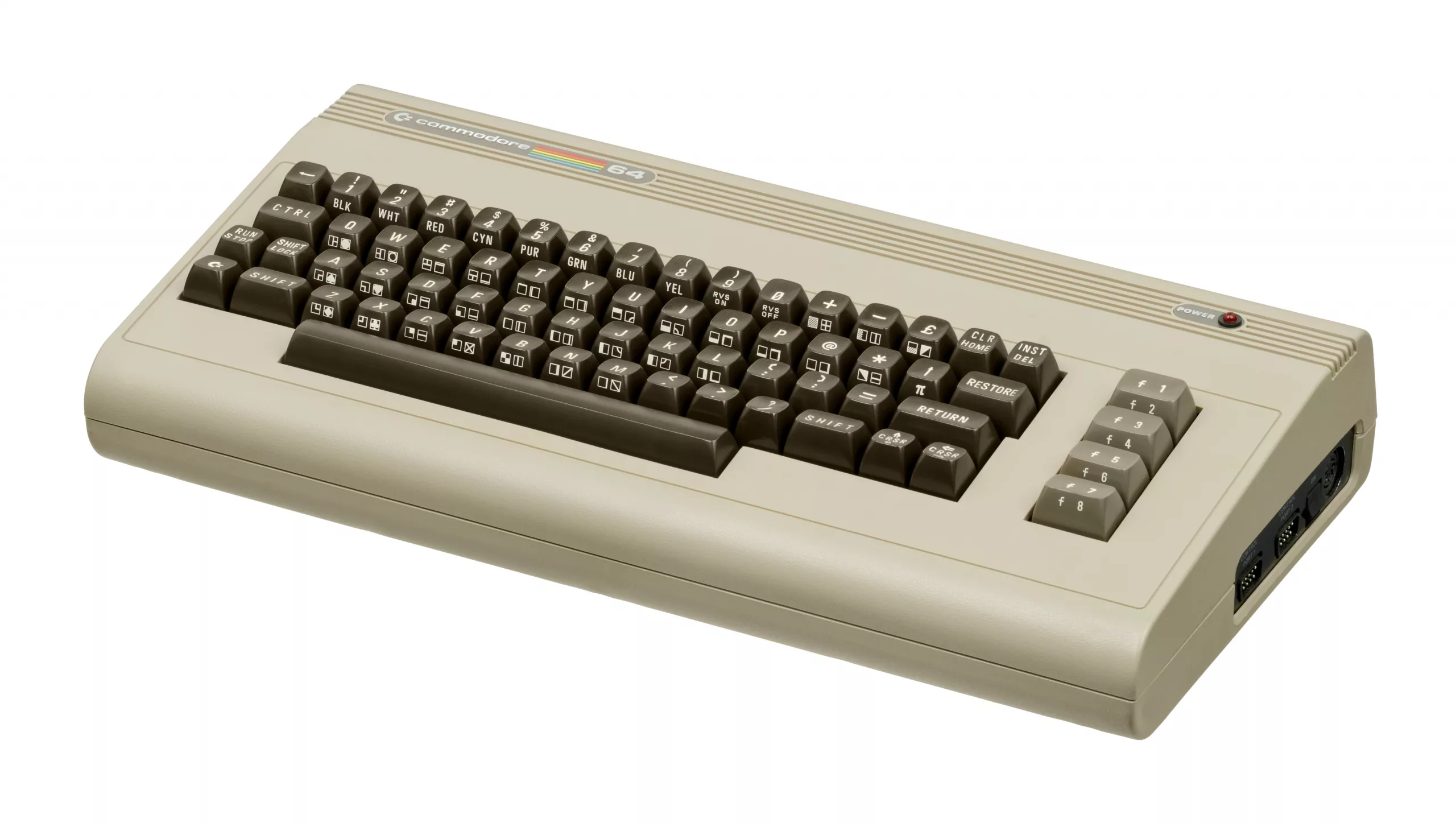
Recapping a breadbin Commodore 64 means replacing every aluminium electrolytic capacitor on the motherboard with a new one of the same capacitance and the same or higher voltage rating, working on one capacitor at a time with the board out of the case. It takes an evening. The step that goes wrong is the desoldering: a pad lifted off a forty-year-old board is the usual casualty, and the technique below is there to stop that happening.
- Blank screen at power-up: the Commodore 64 Service Manual says to check the external power supply first, so test that before you open the machine (see the PSU guide).
- Hum band rolling up the screen, or a wavy picture: the manual lists the external supply and the 5 V regulator VR2 as the first suspects. The smoothing capacitors behind them (C19 on the unregulated 5 V supply, C88 on the 12 V supply) are the next place to look.
- Nothing wrong yet: original electrolytics are well past their design life, so a recap is preventive maintenance as much as a repair.
Which capacitors does a breadbin C64 need?
There is no single C64 capacitor list, because there is no single C64 board. Kit suppliers list separate sets for assemblies 250407 (1983, eight-pin video port), 250425 (1984), 250466 (1986, the last breadbin board) and 250469 (the 1987 short board), and the values are not the same on each. For example, the kit lists for 250425 and 250466 give C88 as 1000 µF 25 V and C90 as 470 µF 25 V, both axial. The Commodore 64 Service Manual (September 1985, part number 314001-02) lists C88 and C90 as 470 µF 50 V on PCB assembly 326298.
The manual’s list for 326298 is still a useful cross-check. It gives C19 as 2200 µF 16 V, C91 as 100 µF 16 V, C88 and C90 as 470 µF 50 V, and 10 µF 25 V for the remaining electrolytics: C8, C12 to C15, C17, C24, C34, C57, C62, C64, C65, C94 and C102. Treat it as a reference, not a shopping list. Open your machine, read the values printed on the cans and match them to your assembly number before you order anything.
Whatever the list says, the replacement rules are the same: identical capacitance, a voltage rating equal to or higher than the original, a 105°C rating where you can get it, and the same lead style (axial or radial) or leads bent to fit. Polarity matters. The stripe on the side of a new electrolytic marks the negative lead.
What do you need to recap a C64?
- Replacement capacitors for your exact board, plus a few spares
- Temperature-controlled soldering iron and leaded solder (it flows at a lower temperature than lead-free and mixes with the old joint)
- Desoldering braid or a pump, and flux
- Isopropyl alcohol and a stiff brush
- A phone or camera, a multimeter and a notepad
How do you recap a Commodore 64 step by step?
- Open the case. Remove the case screws, lift the top half away and disconnect the keyboard and power LED leads.
- Free the board. Lift the motherboard out and take off the metal shield. The service manual lists a PCB shield plate and a PCB insulation sheet, so expect both.
- Photograph both sides. You will want the picture when the capacitors are out.
- Record every electrolytic. Write down the reference number, value, voltage, polarity and whether it is axial or radial. Check each against the assembly number on your board.
- Add fresh solder. Flow new leaded solder onto the old joint on one lead of the first capacitor. It helps the old solder melt and wick evenly.
- Pull the lead while the joint is molten. Do not lever the capacitor. Heat the joint and ease the lead out. Repeat for the second lead.
- Clear the holes. Use braid or a pump so the holes are open and the pads are clean. Do not solder a new lead onto old solder.
- Check for leakage. Brown or white crust under an old capacitor is electrolyte. Clean it with isopropyl alcohol and a brush before fitting anything.
- Fit the new capacitor. Match polarity to your photo and notes, seat it flat and solder both leads. Trim the excess.
- Repeat, one capacitor at a time. Finishing each position before starting the next means you cannot mix up the positions.
- Clean the board. Brush off flux residue with isopropyl alcohol and let it dry.
- Inspect every joint. Look under strong light for bridges, cold joints and lifted pads.
- Refit the shield and the board. Do not connect the original power brick yet.
- Power up from a tested supply. Use a known-good power supply only, and check for a clean picture and the READY prompt. The next section covers what to check.
What if a pad lifts while desoldering?
Stop and do not force it. Scrape a little solder mask off the trace a few millimetres from the pad, tin it, and run a short length of thin wire from there to the component lead on the top side. It is permanent and invisible once the shield is back on. Check continuity with a multimeter between the lead and the far end of the trace before you power the board.
What should you check after recapping a C64?
- Boot to the READY prompt and look for a clean, steady picture with no hum band.
- Measure the 5 V supply before blaming the recap for anything. Per C64-Wiki, the 5 V DC rail should sit between 4.95 and 5.10 V for the machine to work properly.
- Run a RAM test utility rather than trusting the READY prompt.
- Leave the machine running for a while and feel for parts that are hotter than they were before.
- If the screen is blank or a band appears, the service manual still points first at the external supply and VR2, not at your new capacitors.
Sources: Commodore 64 Service Manual (September 1985, PN-314001-02), circuit theory and parts list for PCB assembly 326298; C64-Wiki, “Power Supply”; Retro Rewind capacitor kit pages for assemblies 250407, 250425, 250466 and 250469; RetroTechCollection, Commodore 64 Capacitor Replacement Guide. The values for assembly 326298 are from the service manual; the 250425 and 250466 values are Retro Rewind’s. Read the cans on your own board before ordering.
